
by Alan Parker
CRC Press, CRC Press LLC
ISBN: 0849371716 Pub Date: 08/01/93
|
|
Algorithms and Data Structures in C++
by Alan Parker CRC Press, CRC Press LLC ISBN: 0849371716 Pub Date: 08/01/93 |
| Previous | Table of Contents | Next |
The calculation of overflow for ripple-carry addition can be simplified by analyzing the carry-in and carry-out to the final stage of the addition. This is demonstrated in Table 4.3. An overflow occurs when
| an-1 | bn-1 | sn-1 | cn-1 | cn-2 | Overflow |
|---|---|---|---|---|---|
| 0 | 0 | 0 | 0 | 0 | 0 |
| 0 | 0 | 1 | 0 | 1 | 1 |
| 1 | 1 | 0 | 1 | 0 | 1 |
| 1 | 1 | 1 | 1 | 1 | 0 |

which results in the boolean expression

In order to improve on the performance of the ripple-carry adder the carry-in to each stage is predicted in advance rather than waiting for the carry-in to propagate from the previous stages. The carry-out of each stage can be simplified from Eq. 4.2 to

or

which is written as
with

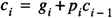
The interpretation of Eq. 4.10 is that at stage i a carry may be generated by the stage, (gi = 1) , or a carry may be propagated from a previous stage, (pi = 1). When gi = 1 stage i will always have a carry-out regardless of the carry-in. When gi = 0 stage i will have a carry when the carry-in is 1 and pi = 1, thus it is said to have propagated the carry. The time required to produce the generate, gi, and the propagate, pi, is 1Δ. For the a four-bit adder as in Figure 4.3 one has


The interpretation of Eq. 4.14 is that a carry-out will occur from stage 3 of the 4-bit adder if it is
The carry of the final stage, c3, can be generated in 2Δ as shown in Figure 4.5. Similarly, the other carries can be calculated in 2Δ or less.
Once the carries are known the sum can be generated within 2Δ. Thus for the four bit adder the sum can be generated in a total of 5Δ with
)
Figure 4.5 Delay Calculation
Using ripple-carry the four bit adder would require 7Δ to form the result. With the CLA adder the carries are thus generated by separate hardware. As is common, speed is thus achieved at the cost of additional hardware. The 4-bit CLA adder module is shown in Figure 4.3.
The CLA approach can be extended to n-bits yielding the following equation for the carry bits
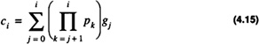
with the product term evaluating to one when the indices are inconsistent. The calculation of the carries in Eq. 4.15 can be accomplished in 2Δ once the generates and propagates are known; however, there is a hardware requirement to be met. For each carry of the stage the implementation in 2Δ requires that the gates have a fan-in (number of inputs, to the gate) of i + 1. For an n-bit CLA adder realized in this manner a gate with a fan-in of n is required. This can be seen in Figure 4.5 where for a 4-bit CLA adder the carry inputs are calculated using a 4-input NAND gate. While this is practical for a 4-bit adder it is not practical for a 64-bit adder. As a result of this an inductive approach is needed to limit the fan-in requirements of the gates to implement the circuit. The timing of the 4-bit CLA adder module is shown in Figure 4.7.
)
Figure 4.6 2’s Complement 4-Bit CLA Adder Module
When an inductive approach is taken the module shown in Figure 4.3 will need to input a carry in to the lowest stage. As a result the basic building block will be as shown in Figure 4.3. The module will be depicted as shown in Figure 4.8. The module serves as a basic building block for a 16-bit CLA adder as shown in Figure 4. 10. For this case there are four groups of CLA-4 building blocks. The carry lookahead hardware module CLM (15 → 0) provides the carry input to each of the groups. This carry is predicted in an analogous fashion to before. Group 0 will generate a carry if it is generated by one of the four individual full adders within the group. One can define group generate, gg0, as

)
Figure 4.7 4-Bit CLA Adder Module Timing
)
Figure 4.8 2’s Complement 4-Bit Module Representation
)
Figure 4.9 2’s Complement 4-Bit CLA Adder Module
and group propagate, gp0, as

Similarly,


)
Figure 4.10 16-Bit CLA Adder with Group Lookahead
From these equations one can derive the group carries as gc0, the carry out of group 0,

gc1, the carry out of group 1,

gc2, the carry out of group 2,

gc3, the carry out of group 3,

The group carries become the carry-in to each of the CLA-4 modules. Each CLA-4 module can calculate the individual carries within 2Δ after the group carries are known.
Code List 4.5 CLA Addition
Code List 4.6 Output of Program in Code List 4.5
This section starts the implementation of a simple hardware simulator in C++. The simulator will be used to simulate the hardware required to implement the algorithms in the previous sections.
| Previous | Table of Contents | Next |
)
)
)
)
)
)
)
)
)
)
)